ABOUT US
PRODUCTS
SOLUTIONS
SUPPORT
NEWS
JOIN US
CONTACT
The cable is designed to be installed on transmission and distribution lines to carry voice, data and video communications, especially in lighting waveform monitoring system, an observation system for overhead test line, maintenance data information system, power line protection system, power line operation system, and unmanned substation monitoring.
• Colored coded fibers and binders for quick and easy identification during installation.
• Compact design results in excellent sag tension performance of the cable.
• Aluminium clad steel wires and Aluminium alloy wires provides mechanical strength to withstand the installation and operating conditions,while achieving conductivity required to control temperature rise, during the short circuit fault condition.
• Optical unit placed inside the Aluminium tube provides exceptional mechanical and thermal protection for the fiber against severe environments and external laternal force.
• Thick walled Aluminium tubes provide hermetic seal for optical units, providing excellent crush resistance and low resistivity.
• Unique design has maximum allowable tension to control fiber strain.
• Stranded wires used for optimizing the mechanical and electrical properties of the cables.
• High load, long span capability.
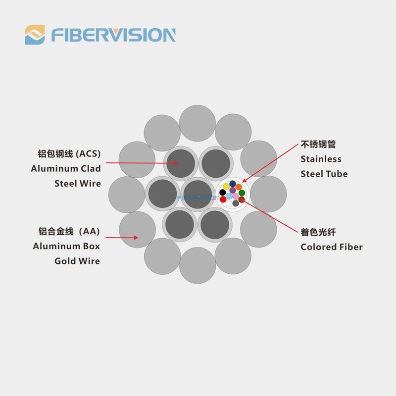
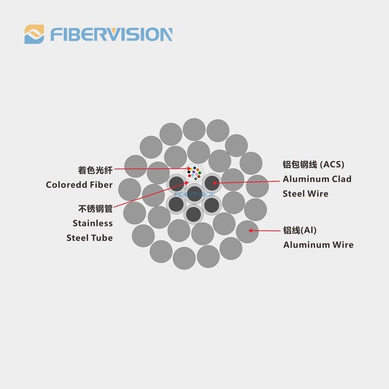
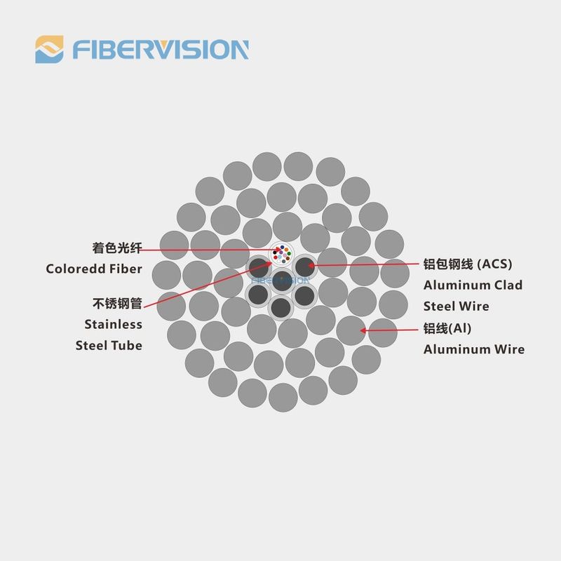
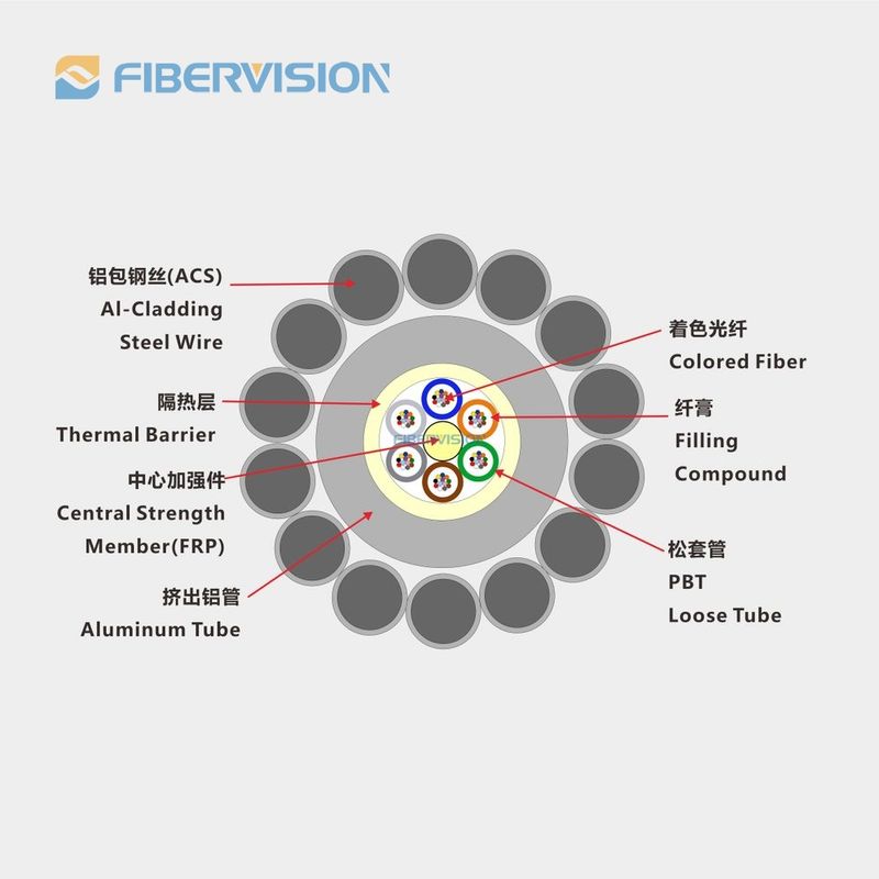
OPGW stands for Optical Ground Wire. OPGW cables consist of a central core formed by one or more layers of optical fibers surrounded by layers of steel or aluminum wires. The steel or aluminum wires serve the dual purpose of providing structural support as well as grounding for the power line. The optical fibers within the cable are protected by these metallic layers, shielding them from environmental factors.
Constructions and Performance
Classification | Material | Value | ||
Construction | Optical Fibre | G652D/G655 etc. | 2 - 144 | |
Stranded | 1-12 PBT Tube | Stranded | ||
Stranded Line | AS wire/AA wire/Al Rod | 1.5 - 6mm | ||
Max. Diameter | 30mm | |||
Max. Cross Section | 500mm2 | |||
Characteristic | According to the standards as DL/T 832, IEC60794-4-10, IEEE1138 | |||
Max. Tensile Strength (RTS ) (kN) | 700 | |||
Max. Crush Strength(N/100mm) | 3000 | |||
Max. Short Current Capacity (40℃ to 200℃)(kA2s) | 2000 | |||
Min. Bending Radius (Dynamic) | 20D | |||
Min. Bending Radius (Static) | 15D | |||
Environment Performance | Installation (℃) | -10 to +50 | ||
Transportation and Operation (℃) | -40 to +65 | |||
Optical Fibre Characteristics
Attenuation | Bandwidth | Polarization Mode Dispersion | ||||||
@850nm |
@1300nm |
@1310nm |
@1550nm |
@850nm |
@1300nm | Individual Fibre | Design Link Value (M=20, Q=0.01%) | |
G652D | — | — | ≤0.35dB/km | ≤0.21dB/km | — | — | ≤0.20ps/ km | ≤0.1ps/ km |
G655 | — | — | — | ≤0.22dB/km | — | — | ≤0.20ps/ km | ≤0.1ps/ km |
50/125μm | ≤3.0dB/km | ≤1.0dB/km | — | — | ≥600MHz.km | ≥1200MHz.km | — | — |
62.5/125μm | ≤3.5dB/km | ≤1.0dB/km | — | — | ≥200MHz.km | ≥600MHz.km | — | — |